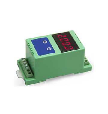
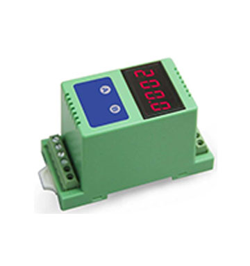
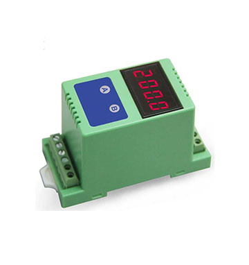
0-10V/4-20mA to RS485/RS232 Display Control Smart Sensor (AD Conversion Smart Control): ISO 4021 (LED1) Series
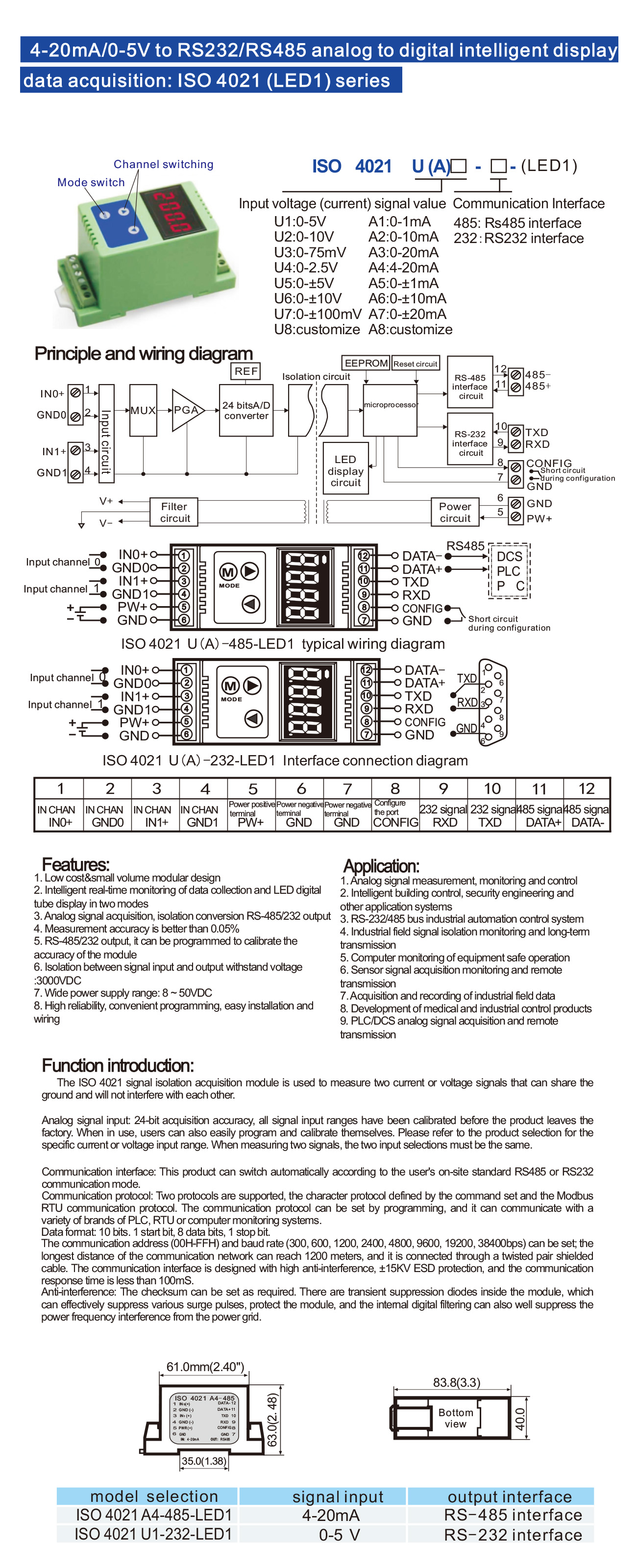
Sunyuan ISO 4021 series intelligent data acquisition, display and control module can realize signal safety isolation and high precision data acquisition, isolated display and monitoring between sensor and host. The product integrates isolation, display, alarm control and transmission, and is often used in RS-232/485 bus industrial automation control system, 4-20mA / 0-10V signal measurement, monitoring and intelligent control, small signal measurement, and remote monitoring occasions such as industrial field signal isolation and long line transmission. Through the software configuration, it can access a variety of sensor types, including current output type, voltage output type, etc..
ISO 4021 series intelligent data acquisition, display and control products include power supply isolation, signal isolation, linearization, A/D conversion, digital display and RS-485 serial communication modules. Each serial port can be connected to a maximum of 256 ISO AD series modules, using ASCII code character communication protocol or MODBUS RTU communication protocol of the standard common communication methods, its instruction set compatible with the ADAM module, the baud rate can be set by the user, and can be hooked up with the control modules of other manufacturers on the same RS-485 bus, which is convenient for the host computer to program.
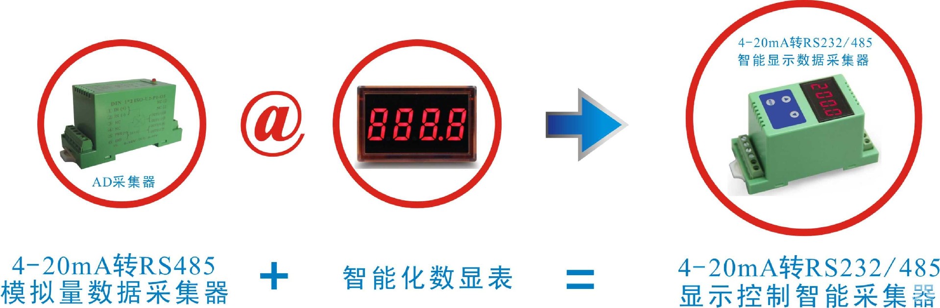
ISO 4021 Series Intelligent Data Acquisition Display and Control products are intelligent monitoring and control systems based on microcontrollers. All user-set configuration information such as calibration values, address, baud rate, data format, checksum and status are stored in non-volatile memory EEPROM. The analog signal is isolated and amplified for AD conversion, and at the same time has the signal display function. The product adopts intelligent design, with a variety of functions that traditional products do not have. With only a single power supply, the analog signal can be isolated and converted, and displayed in decimal digital quantities according to the set range in linear correspondence. The traditional embedded analog display meter adopts potentiometer adjustment, which has a single adjustment parameter, is not flexible and is greatly affected by temperature. Compared with the traditional analog display meter, this embedded intelligent digital display meter is controlled by the central processor CPU, and through the configuration of software control, it can realize the setting of various parameters such as zero point, full scale, data format, communication protocol, etc., which is highly flexible and practical. The digital display meter adopts LED display board and has reverse and over-current protection function. The product is widely used in industrial control, petrochemical, environmental protection, smart home, mining and other industries for monitoring and control of temperature physical quantity control points.
Function Introduction
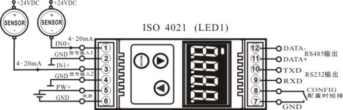
ISO 4021 (LED1) series intelligent signal isolation acquisition module can be used to measure one way voltage or current signal, can also be used to measure two ways can be common ground and will not interfere with each other current or voltage signal. The data acquisition results are displayed in two modes via LED digital tubes.
24-bit acquisition accuracy, analog signal input. All signal input ranges are fully calibrated before delivery. Users can also easily program their own calibration when in use. For specific current or voltage input ranges, please refer to the product selection, and both input selections must be the same when measuring two signals.
1、 Communication protocol
Communication interface: 1 channel standard RS-485 communication interface and 1 channel standard RS-232 communication interface.
Communication protocol: Support two protocols, ASCII character protocol and MODBUS RTU communication protocol. It can be programmed to use that kind of communication protocol, which can realize network communication with many brands of PLC, RTU or computer monitoring system.
Data format: 10 bits, 1 start bit, 8 data bits, 1 stop bit.
Communication address: (00H-FFH) and baud rate (300, 600, 1200, 2400, 4800, 9600, 19200, 38400bps) can be set; the longest distance of the communication network can be up to 1200 meters, connected by twisted shielded cable. Communication interface high anti-interference design, ± 15KV ESD protection, communication response time is less than 100mS.
2, anti-interference
Checksum can be set as required. Transient suppression diodes inside the module can effectively suppress various surge pulses to protect the module, the internal digital filtering, can also be a good suppression of industrial frequency interference from the power grid.
Note: ISO 4021 (LED1) series products also support RS23 and RS485 communication interface output, users can choose the corresponding communication interface according to the use of the environment, but only one of the two interfaces can work online at the same time, otherwise, it will cause interference.
Product Selection Examples
Example 1, Two-channel signal input: 4-20mA; Auxiliary power supply: 24VDC; Output: RS23 and RS485 communication; LED display.
Model No.: ISO 4021-A4-LED1
Example 2, 2-channel signal input: 0-±20mA; Auxiliary power supply: 12VDC; Output: RS23 and RS485 communication; LED display.
Model No.: ISO 4021-A7-LED1
Example 3, 2-channel signal input: 0-5V; Auxiliary power supply: 12VDC; Output: RS23 and RS485 communication; LED display.
Model No.: ISO 4021-U1-LED1
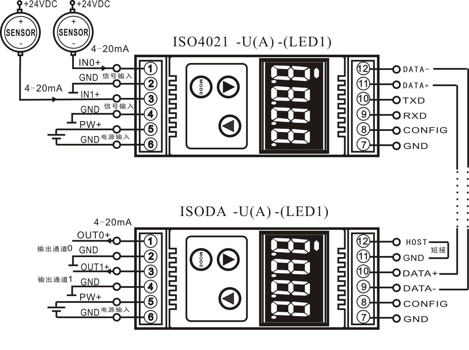
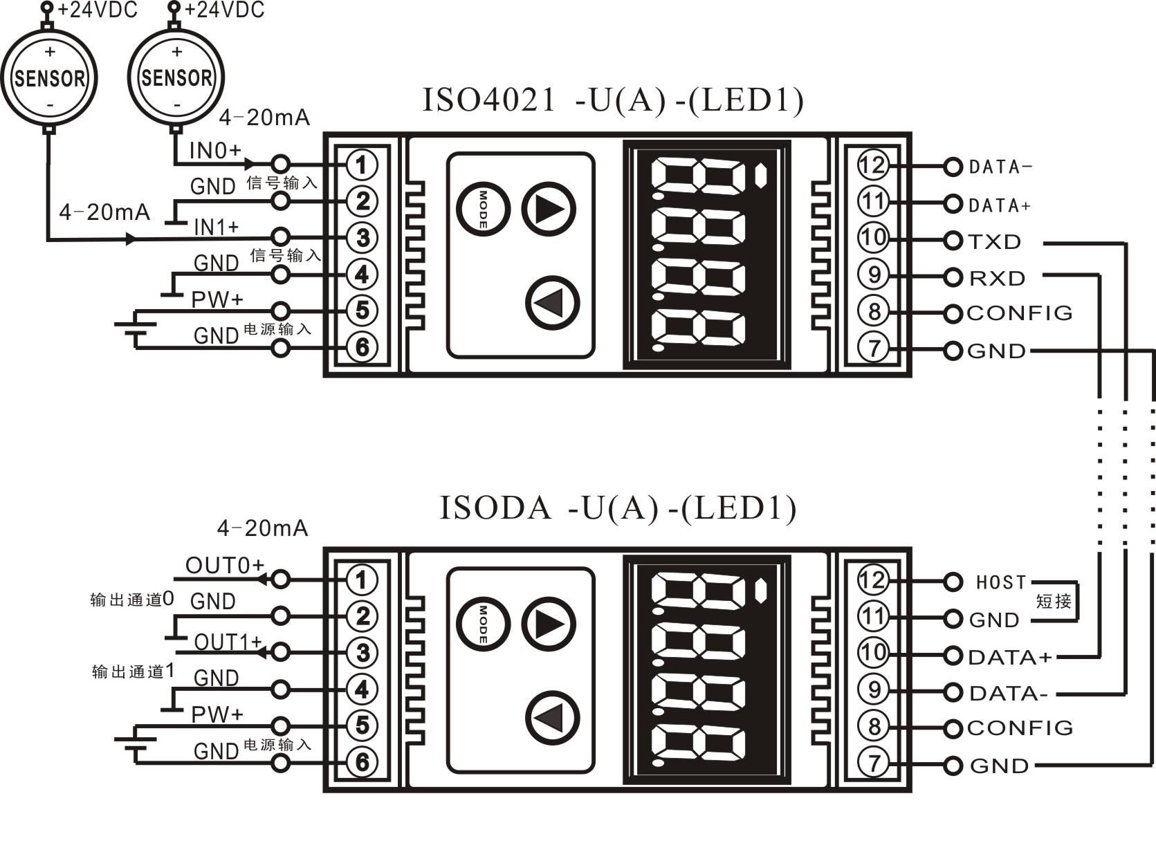
Typical Application Wiring Diagram
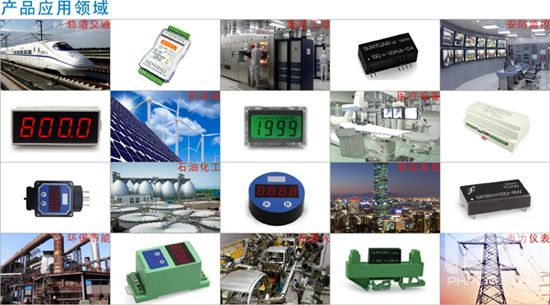
Product Design Portfolio Image
Typical Application Diagram of ISO 4021 (AD conversion) inline with ISO DA (DA conversion)
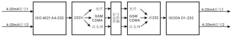
Signal remote transmission application examples
1, ISO 4021 and ISO DA RS485 communication mode application wiring diagram
2、ISO DA与ISO 4021的RS232通讯方式应用接线图
Initializing the ISO 4021 (LED1)
When connecting to an RS-232/RS-485 network, the ISO 4021 (LED1) module must be assigned a unique address code, which is a hexadecimal number that takes values between 0x00 and 0xFF. All new ISO 4021 (LED1) modules use the same factory initial settings, as shown below:
Address code 01H
Baud rate 9600 bps
Checksum disabled
ASCII character communication protocol
Since the new modules all have the same address code, their addresses will contradict the other modules, so you will have to reconfigure each module's address when you set up your system. You can modify the address of the ISO 4021 (LED1) module by using configuration commands after connecting the ISO 4021 (LED1) module power cable and RS485 communication cable. Baud rate, parity and status, communication protocol also need to be adjusted according to the user's requirements. Before modifying the baud rate, checksum status and communication protocol, the module must be put into the configuration state first, otherwise it cannot be modified.
How to let the module enter the configuration state
ISO 4021 (LED1) modules have a special pin labeled CONFIG. The module enters the configuration state when the CONFIG pin is shorted to ground (GND pin) and the power is turned on. In this state, the module is configured as follows:
Address code 00H
Baud rate 9600 bps
Prohibit checksum
ASCII character communication protocol
At this point, the baud rate, parity and status parameters of the ISO 4021 (LED1) module can be modified by configuration commands, and the communication protocol can also be selected by setting the module's communication protocol command. When you are not sure about the specific configuration of a module, you can also install a configuration jumper to make the module enter the configuration state and then reconfigure the module. If the user needs to set the module to MODBUS RTU communication protocol, please see the relevant instructions in the MODBUS communication protocol section.
ISO 4021 (LED1) Module Calibration
Calibration must be performed under the ASCII character communication protocol. calibration is not supported under the Modbus protocol.
The product has been calibrated at the factory and can be used directly without calibration. You may recalibrate the module during use. During calibration, the module needs to be inputted with appropriate signals, and different input ranges require different input signals.
In order to improve the calibration accuracy, it is recommended to use the following equipment for calibration:
1, a DC voltage/current signal source with a stable output and very low noise level
2, a 5 ½ digit or higher precision voltage/current measuring instrument to monitor the accuracy of the input signal
Calibration process
1、Select the input channel to be calibrated and connect the corresponding input signal according to the input range of the module.
2、In which ISO 4021 (LED1) module zero is calibrated at input 0, and fullness is calibrated at 120% of input fullness.
3, such as 4-20mA input, calibration zero input 0mA, calibration fullness input 24mA. (0-5V input, calibration zero input 0V, calibration fullness input 6V).
4, to the analog input module needs to be calibrated channel input zero signal, usually 0mA or 0V.
After the signal is stabilized, send the offset calibration $AA1N command to the analog input module (N stands for the code of the channel currently being calibrated, 0 or 1).
6, to the analog input module to be calibrated channel input 120% of the fullness of the current or voltage signal.
7、After the signal is stabilized, send the gain calibration $AA0N command to the analog input module (N represents the channel code currently being calibrated, 0 or 1).
8、Calibration completed
About the use of LED digital tube display instructions
ISO 4021 (LED1) is an analog data acquisition module with display, which displays the collected analog voltage or current value through the four-digit LED digital tube, so that users can easily check the current collected value. If the display is not required, the user can turn off the display by using the MODE key. After the display is turned on, two display modes are used, i.e., single-channel display and multi-channel cyclic display.
The display data format is as follows: channel number, symbol sign, three data bits; the data bits are divided into integer and decimal parts, separated by decimal points. The first from the left for the channel number (1-2), the channel number followed by a decimal point to do the symbol sign bit, the decimal point is bright on behalf of the current collection of data is a positive value, if the decimal point is off, on behalf of the current collection of data is a negative value. The last three digits are the decimal value of the collected data.
Display Mode
Switch the display mode through the mode switching key (MODE key), after pressing the mode key, the LED briefly displays C1 on behalf of the current mode is a single-channel display mode, and briefly displays C2 on behalf of the current mode is a multi-channel cyclic display mode.
C1: single-channel display, in this mode, the LED only displays the collected value of one channel at a time (the channel number indicates which channel's data is displayed), and the display channel is switched by the two channel switching buttons above the mode key, after the left button is pressed, the display channel number is increased by one, and after the right button is pressed, the display channel number is decreased by one.
C2: Multi-Channel Cyclic Display, in this mode, the LED displays the collected values of each channel cyclically at fixed time intervals, if you need to switch the display mode or turn off the display, just press the mode key (MODE).