 Bus RS232 / RS485 to 0-20mA / 0-10V Display Control Smart Sensor (DA Conversion Smart Control): ISO DA (LED1) Series
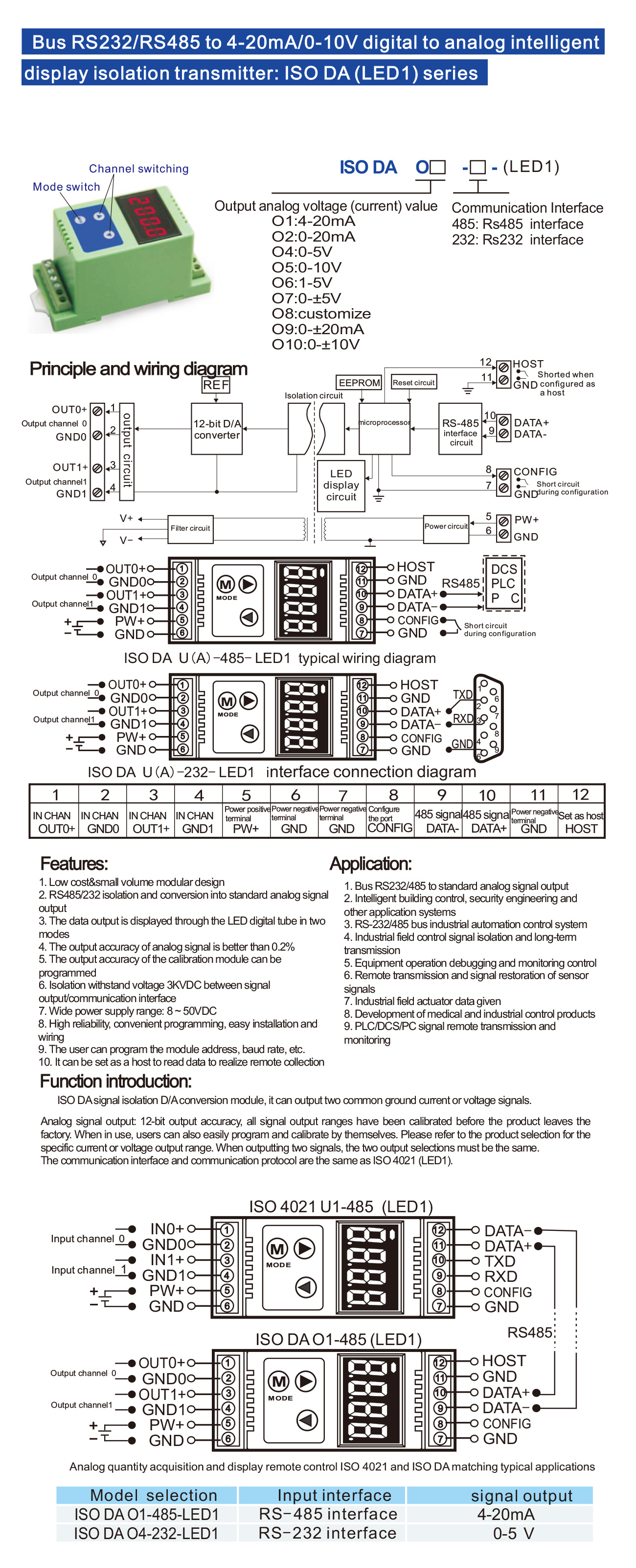
ISO DA (LED1) series products can realize the host RS485 or RS232 interface signal isolation into a standard analog signal, used to control remote equipment. And can real-time display output analog signal value. The products can be used in RS232/RS485 bus industrial automation control system, the computer serial communication signals into 4-20mA (0-10V) and other standard analog signal output, used to control the industrial field of the implementation of the device, instrumentation, PLC / DCS / FCS / PCC, etc..
Products include power isolation, signal isolation, linearization, D/A conversion, display and RS485 serial communication. Each serial port can be connected to a maximum of 256 ISODA series modules, the communication method adopts ASCII code communication protocol or Modbus RTU communication protocol, its instruction set is compatible with the ADAM module, the baud rate can be set by the code, and it can be hooked up to the same RS485 bus with the control modules of other manufacturers, which is convenient for computer programming.
ISO DA (LED1) is an intelligent monitoring and control system based on a microcontroller. All user-set configuration information such as calibration values, address, baud rate, data format, checksum and status are stored in non-volatile memory EEPROM. The product is designed and manufactured according to industrial standards, and the signal output and communication interface can withstand 3000VDC isolation voltage, strong anti-interference ability and high reliability. Operating temperature range - 25℃~+70℃.
ISO DA (LED1) Function Introduction
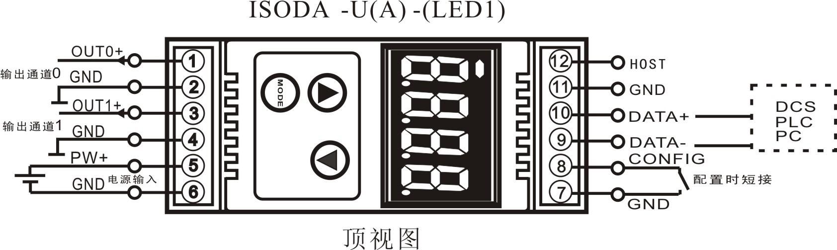
ISO DA (LED1) signal isolation D/A converter module, can be used to output a voltage or current signal, can also be used to output two can be common ground current or voltage signal, and real-time display output analog signal value.
Analog Signal Output
With 12-bit output accuracy, all signal output ranges have been fully calibrated before the product leaves the factory. In use, the user can also easily program their own calibration.
For specific current or voltage output range, please refer to the product selection, and when outputting two signals, the two output selections must be the same.
Communication protocol
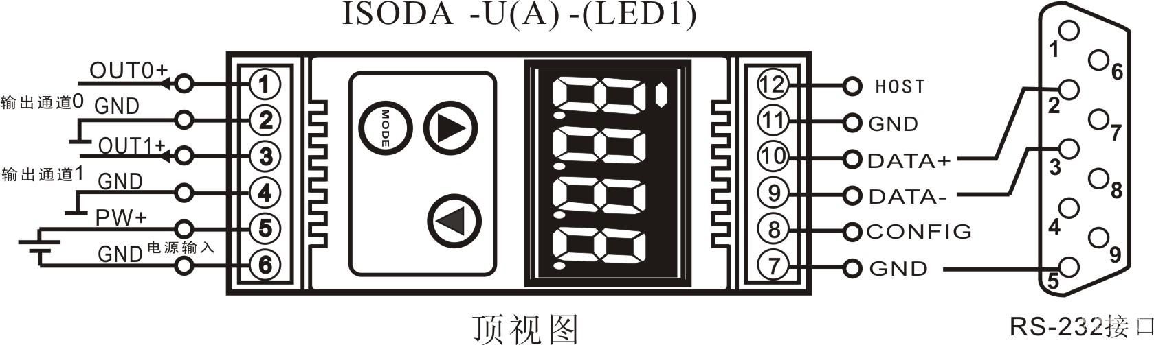
Communication interface: 1-channel standard RS485 communication interface or 1-channel standard RS232 communication interface, specify the communication mode when ordering.
Communication protocol: two protocols are supported, the character protocol defined in the command set and the Modbus RTU communication protocol. It can be programmed to use that kind of communication protocol to realize network communication with PLC, RTU or computer monitoring system of various brands.
Data format: 10 bits. 1 start bit, 8 data bits and 1 stop bit.
Communication address (0~255) and baud rate (300, 600, 1200, 2400, 4800, 9600, 19200, 38400bps) can be set; the longest distance of communication network can be up to 1200 meters, connected by twisted shielded cable.
Communication interface high anti-interference design, ±15KV ESD protection, communication response time less than 100mS.
Anti-interference
Checksum can be set as required. Transient suppression diodes inside the module can effectively suppress various surge pulses and protect the module, and the internal digital filtering can also well suppress the industrial frequency interference from the power grid.
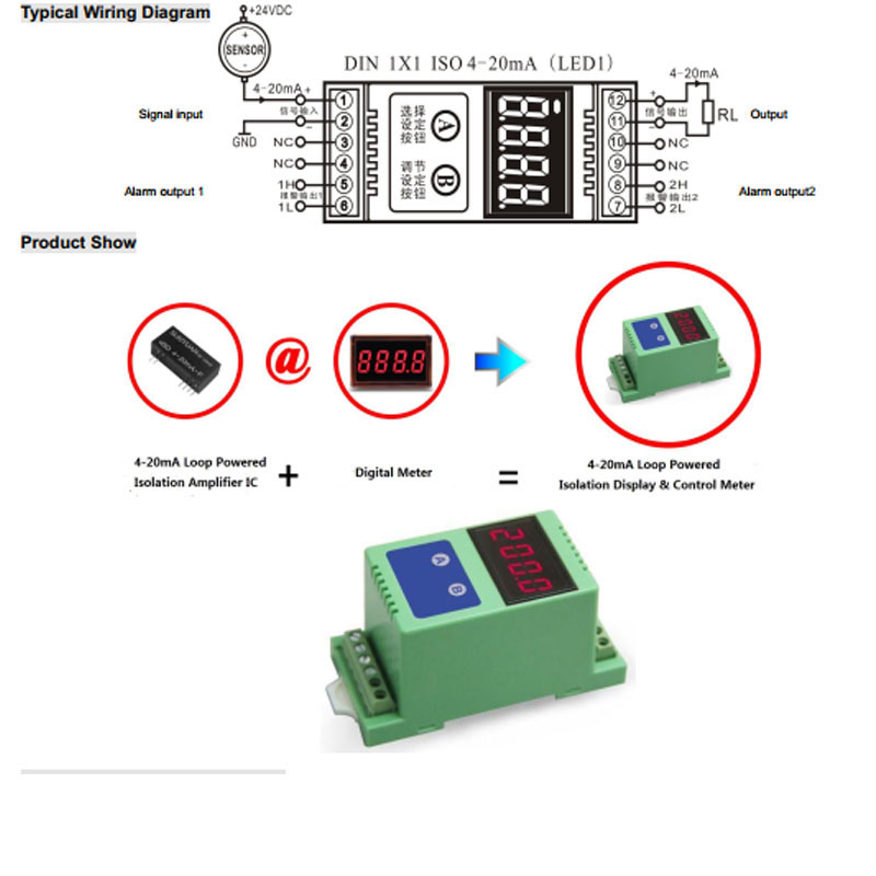
Typical application diagram
Selection example 1, Type: ISO DA O1 -485 LED; indicates 4-20mA signal output, input for RS485 communication, with LED display.
Selection example 2, Type: ISO DA O4 -232 LED; for 0-5V signal output, input for RS232 communication, with LED display.
Option 3, Type: ISO DA O7 -232 LED; indicates 0-±5V signal output, input for RS232 communication, with LED display.
Initializing ISO DA modules
All ISO DA modules that use an RS485 network must be assigned a unique address code, which is a hexadecimal number between 00 and FF. However, all brand new ISO DA modules use a factory initial setup as shown below:
Address code 01
Baud rate 9600 bps
Checksum disabled
Since the new modules all have the same address code, their addresses will contradict the other modules, so when you set up your system, you will have to reconfigure each analog output module address. You can modify the ISODA module address by configuration commands after connecting the ISODA module power cable and RS485 communication cable. Baud rate, checksum status, and communication protocol also need to be adjusted according to the user's requirements. Before modifying the baud rate, checksum status and communication protocol, the module must be put into the default state first, otherwise it cannot be modified.
How to let the module enter the default state
ISO DA modules have a special pin labeled CONFIG. Short the CONFIG pin to ground (GND pin) and then turn on the power, then the module will enter the default state. In this state, the module is configured as follows:
Address code 00
Baud rate 9600 bps
Prohibit checksum
At this point, you can modify the baud rate, checksum status and other parameters of the ISODA module through the configuration commands, and select the communication protocol by setting the communication protocol command of the module. When you are not sure about the specific configuration of a module, you can also install configuration jumpers to bring the module into the default state and then reconfigure the module. If the user needs to set the module to MODBUS RTU communication protocol, please see the relevant instructions in the MODBUS communication protocol chapter.
Notes on the use of LED digital tube display
ISO DA-LED is a digital to analog output module with display, which displays the output analog voltage or current value through a four-LED digital tube, which is convenient for users to check the current output value. If the display is not required, the user can turn off the display by using the MODE key. After the display is turned on, two display modes are used, i.e., single-channel display and multi-channel cyclic display.
The display data format is as follows: channel number, symbol sign, 3 data bits; the data bits are divided into integer and decimal parts, separated by decimal points. The first bit from the left is the channel number (1-2), the channel number is followed by a decimal point to do the symbol sign bit, the decimal point is lighted on behalf of the current data is a positive value, if the decimal point is off, on behalf of the current data is a negative value. The last 3 bits are the decimal value of the output data.
Display Mode
Switch the display mode through the mode switching key (MODE key), after pressing the mode key, the LED briefly displays C1 on behalf of the current mode is a single-channel display mode, and briefly displays C2 on behalf of the current mode is a multi-channel cyclic display mode.
C1: single-channel display, in this mode, the LED only displays the output value of one channel at a time (the channel number indicates which channel's data is displayed), and the display channel is switched by the two channel switching keys below the mode key, the left key is pressed to display the channel number plus one; the right key is pressed to display the channel number minus one.
C2: Multi-Channel Cyclic Display, in this mode, the LEDs display the output values of each channel cyclically at fixed time intervals, if you need to switch the display mode or turn off the display, just press the mode key (MODE).
Calibration Module
The product has been calibrated at the factory and can be used directly without calibration.
You can also use the calibration function to recalibrate the module during use. During calibration, the module requires a high precision multimeter to monitor the output of the module.
In order to improve the calibration accuracy, it is recommended to use the following equipment for calibration:
1. A 5½-digit or higher precision voltage/current measuring meter to monitor the accuracy of the output signal
Calibration procedure
1. Select the output channel to be calibrated and connect the corresponding voltage or current measuring instrument according to the output range of the module. 2.
2. Set the output zero signal of the channel to be calibrated by the analog output module, usually 0mA, 4mA or 0V. Set the analog output by the first command in the command set, and adjust the output signal displayed in the measuring instrument to be the zero point value.
3. After the signal is stabilized, send the offset calibration $AA1N command to the analog output module (N stands for the code of the channel currently being calibrated, 0 or 1).
4. Set the output fullness signal of the channel to be calibrated by the analog output module. Set the analog output through the first command in the command set, and adjust the output signal displayed in the measuring instrument to the full scale value. 5.
5. After the signal is stabilized, send the gain calibration $AA0N command to the analog output module (N stands for the code of the channel currently being calibrated, 0 or 1).
6. Calibration is complete
Modbus RTU Communication Protocol
The factory default protocol of the module is character communication protocol, if you need to set the module to Modbus RTU communication protocol, please follow the steps below to set it:
1、 Short the CONFIG pin (pin 8) and GND pin (pin 7).
2. Connect the power cable and communication interface cable correctly.
3. Turn on the power, the module automatically enters the default state, the communication address is 00, the baud rate is 9600.
4. Wait for 1 minute to initialize the module.
5、 Send command $00P1(cr), check the answer, if it is !00 (cr), then the setting is successful.
6、 Turn off the power, disconnect the connection between CONFIG pin and GND pin.
7. The module has been successfully set to Modbus RTU communication protocol mode.
The Modbus function codes supported by the module are 03 and 06. Please refer to Table 4 for the correspondence between Modbus data content and output, which is the same as that of the character protocol when the data format is hexadecimal complement.
Host mode
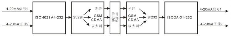
The ISO DA module can be set to host mode by shorting the HOST terminal to the GND terminal (i.e., pin 11 and pin 12 are shorted), connecting it to the communication interface of the ISO 4021 module, and setting the ISO 4021 module to the Modbus communication mode, then it can realize that the two input signals of the ISO 4021 can correspond to the output signals in the two output channels of the ISODA module. This mode is mainly used for digital remote transmission and reduction of analog signals, and is widely used in the fields of fiber optic transmission, GSM, CDMA wireless transmission and Ethernet transmission.
Host mode setting method:
1, When the module is not powered on, short the HOST terminal to GND terminal (i.e. pin 11 and pin 12 are shorted).
2, Turn on the power, power on the module, the module will enter the host mode, and it will send out the command to read the register data according to Modbus protocol continuously.
3, Note that, to enter the host mode, the CONFIG pin should not be shorted to ground (GND pin), otherwise it will enter the default mode.
ISO 4021 (AD conversion) and ISO DA (DA conversion) online typical application diagrams
1、Signal remote transmission application example
2、Wiring diagram of RS485 communication mode between ISO DA and ISO 4021
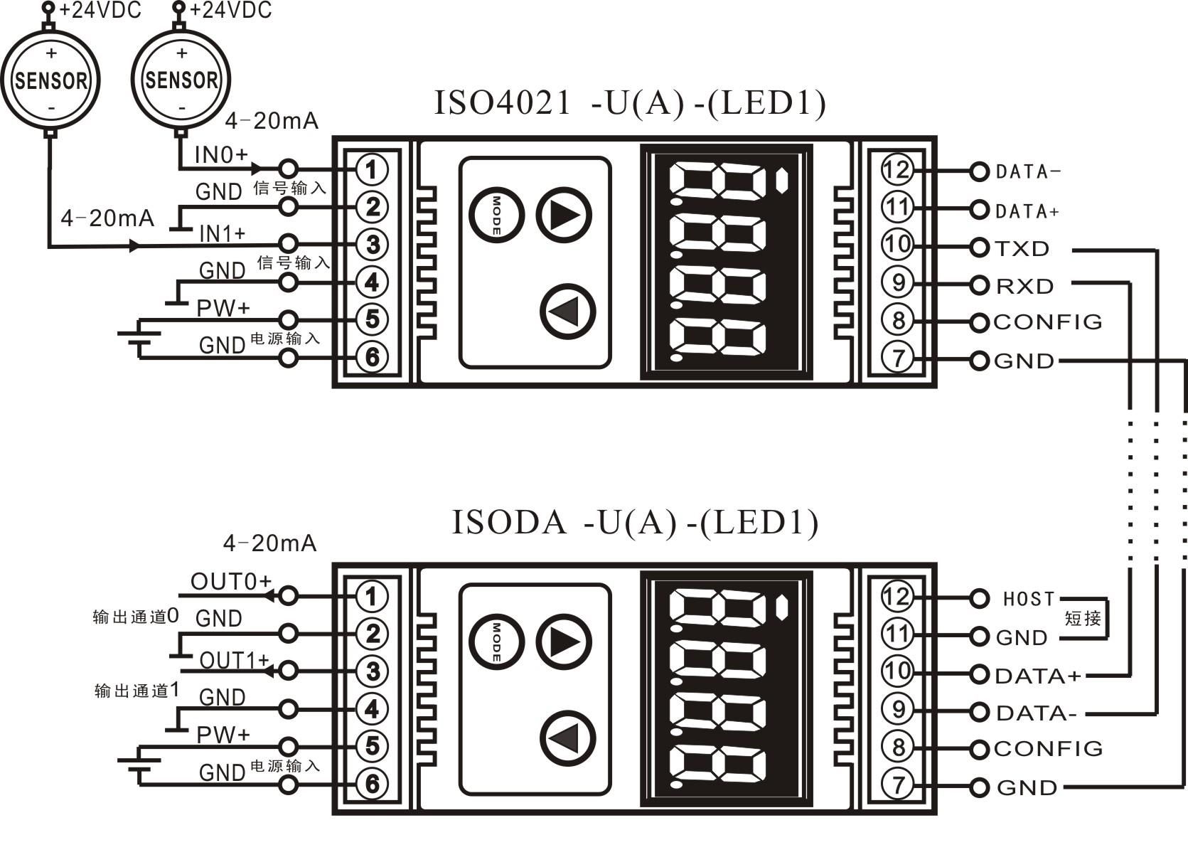
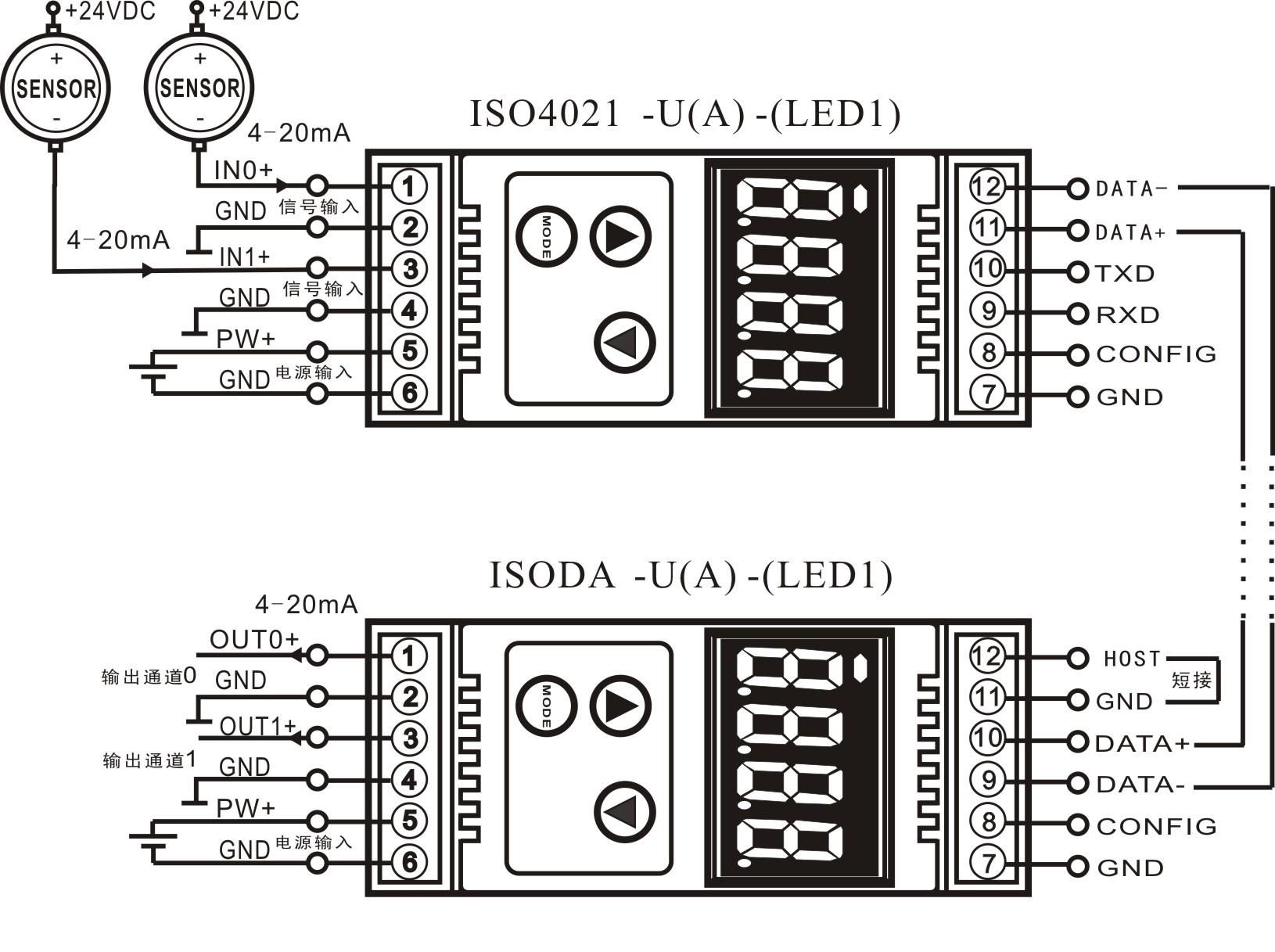
![20180202055316323[1].jpg](/static/upload/image/20230824/1692864320163105.jpg)